
Whether you are in the working sphere of radio technology or simply building an electronic circuit board, you may discover you have the need for an RF directional coupler. This device is designed to help divert, or couple, a certain amount of usually electromagnetic power off of the flow in a line. This kind of coupler is a passive device, which means it should not contribute energy or gain power as it functions.
The Fundamentals of Directional Couplers
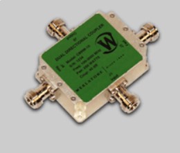
An RF directional coupler can become complex, but at a base level, there are only four elements to consider.
1. The first port is often called the input port or the incidental port. It is where the supply of energy enters the coupler.
2.
The second port is usually named the output port, but sometimes it is
called the transmitted port. This port is the main point where energy
exits the coupler.
3. The third port is the coupled port, also known
as the forward coupled port. This is where the diverted energy from the
main supply will exit the coupler.
4. The fourth port is referred
to as the isolated part, or occasionally the reverse coupled port.
Usually, there will be a termination load to externally or internally
match the energy and complete the port.
Essentially, the coupled port takes the power that has been split from the central energy line running between the input and output ports. It diverts the energy to another circuit, usually. Make sure to remember that the coupled port is only intended to take a smaller amount of energy than the mainline contains.
An Important Point to Remember
As you build a circuit system or radio, keep in mind that the power flowing through this type of coupler can only go in one direction. Therefore, you cannot send energy into the coupler through the coupled port.
Related Posts
- The Energy Of Affiliate
- The Greatest Free Web site Builder Of 2018
- The Best Free Web site Builder Of 2018
- The Power Of Affiliate
- The Best Free Website Builder Of 2018